Break Bracket
|
|
This was the second object we created using Inventor. The 'blueprint' was already created for us, so we just had to follow it and build the object ourselves.
|
|
|
|
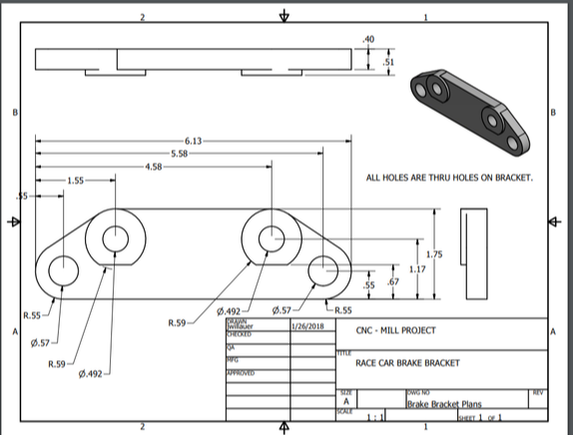
This is the blueprint. I used it to create my break bracket, and you can use it too. If you need more in-depth explanation on how I built the bracket, the rest of this page is a step-by-step explanation of how I built mine.
|
|
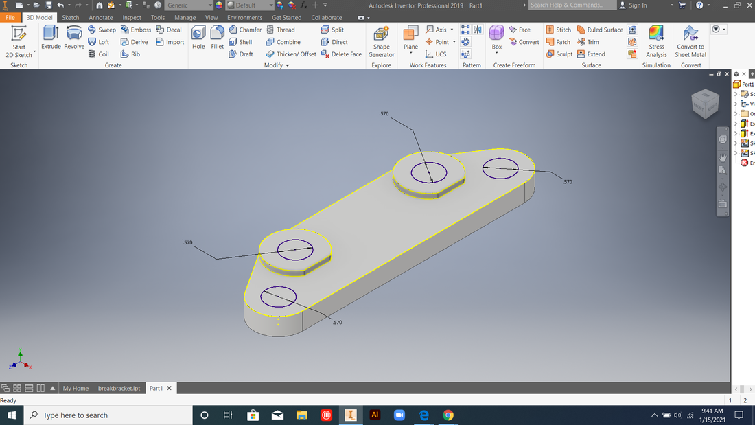
Start a new 2D sketch. Focus on using rectangles and circles, don't worry about the slanted lines yet. Remember to check the blueprint for the correct dimensions!
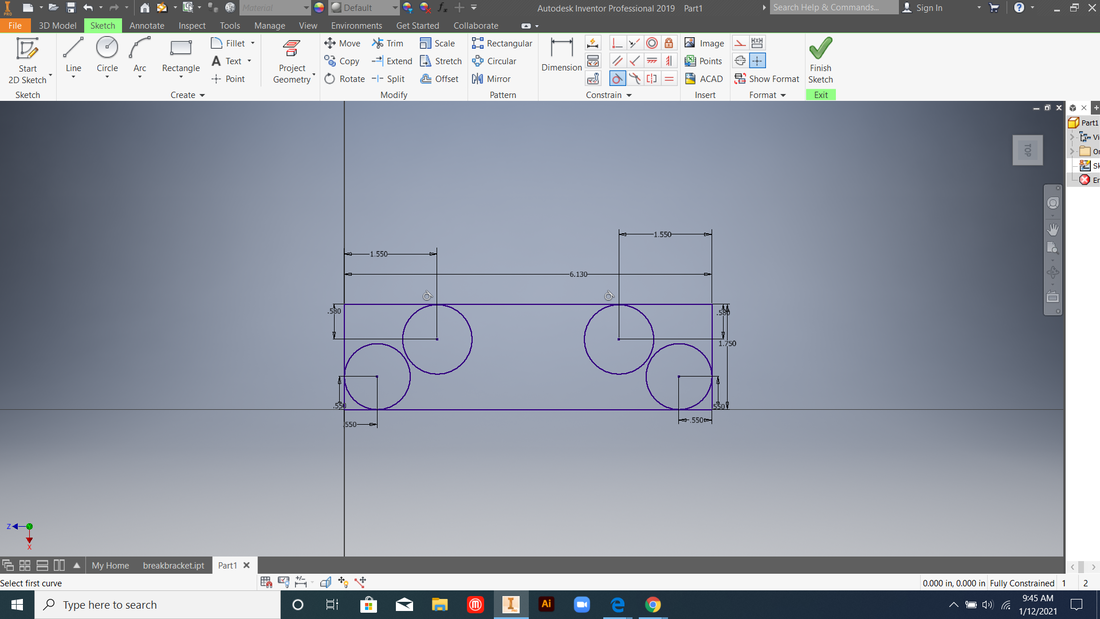
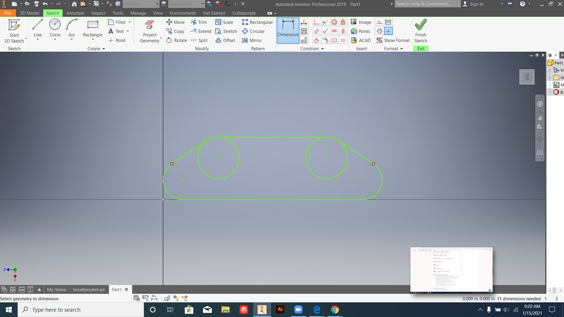
Trim the lines you created in the last step, as well as the extra bits of the lower pair of circles. This may mess with your drawing, so it might help you to remove all the dimensions from step one. Don't forget to trim the corners about the topmost circles.
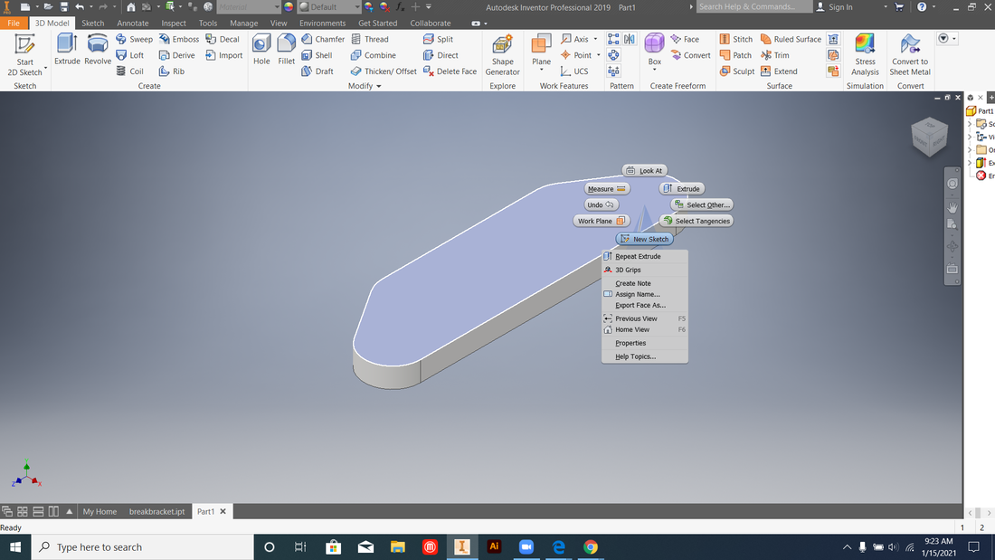
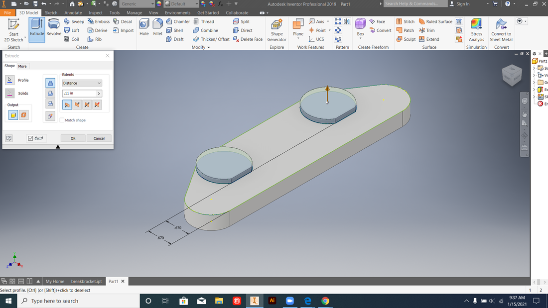
Finish the sketch and use the extrude tool to expand the sketch to a 3D object. Then select the top surface and start a new sketch on the surface.
Draw the last four circles on the top surface of the main section and the raised circles. Use the project geometry tool for placement and the blueprint for size.
|
Use the line tool to manually put in the slanted lines. Use the tangent tool to make them align with the edge of their corresponding circles.

Once you've trimmed everything that needs to be trimmed, go back and put the dimensions back onto the drawing. Do this until the sketch has turned blue again.

Create the second two circles using the project geometry tool to determine the centers. To make the cuts on the bottom of the circles, use the line tool again. Draw the line, dimension it to be in the correct spot, then trim. It won't take as long as the slanted parts did. After you finish the sketch, extrude.
Extrude. Since they're holes, make sure you're doing a negative extrude as opposed to a positive extrude. The holes go straight through the bracket, so it doesn't matter how much they are extruded as long as they pass through it completely.
|
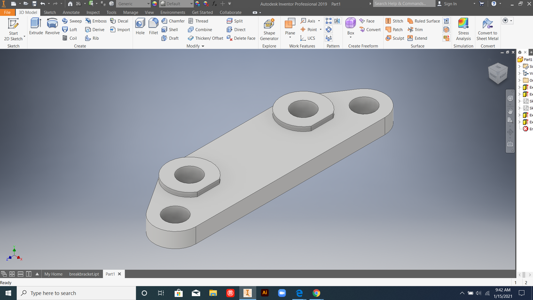
All Done!
|
|
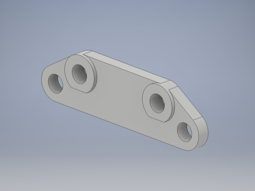
Make sure to save it in your computer files so that you don't lose it.
|
|
